
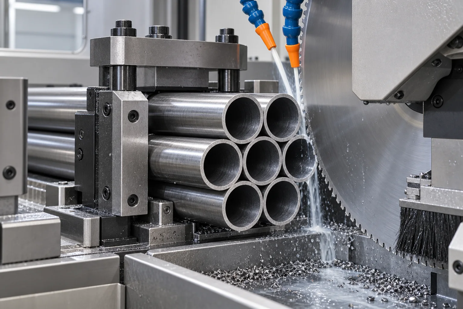
Why A Tube Bundle Cuts Differently
A single round tube gives the blade two main wall crossings during much of the cut. In a bundle, the number of tooth contacts changes continuously as the blade passes through several tube walls and gaps. This interrupted engagement can increase impact at the cutting edge.
The tubes also push against one another. If the clamp holds only the outside of the bundle, an internal tube may still rotate or shift slightly. That micro-movement can show up as noise, tooth chipping, an inconsistent cut face or heavier exit burr.
Four Checks Before Changing The Blade
- Record the actual bundle layout. State the number of tubes, row arrangement, total bundle width and height, and whether spacers or straps are used. The same tube can produce a different engagement pattern in a 3-tube row and a compact 7-tube pack.
- Confirm tube dimensions and material. Send outside diameter, wall thickness, material grade and whether the tube is welded or seamless. A thin wall and a thick wall should not be treated as the same application.
- Check how many teeth engage through the cut. Tooth pitch must suit the changing total wall section. Too coarse a pitch can create impact and snagging; an excessively fine pitch can restrict chip space and increase rubbing.
- Inspect clamping, support and cut-off control. The bundle should remain stable close to the cutting line. Check clamp faces, pressure, nesting, support on both sides and whether the cut-off section can move before the blade exits.
Symptom-Based Troubleshooting
| Observed Symptom | Possible Causes To Check | Useful Evidence |
|---|---|---|
| Random tooth chipping | Tube movement, coarse tooth pitch, sudden feed impact, loose cut-off piece, spindle or flange runout. | Broken-tooth location, bundle video, blade body marks, clamp position and machine parameters. |
| Heavy or uneven burr | Unstable support, worn cutting edge, unsuitable pitch, runout, feed variation or movement near blade exit. | Entry- and exit-side photos from several tubes, not only the best cut. |
| Blue heat marks | Rubbing, insufficient coolant at the tooth-entry zone, recutting chips, worn edge or unsuitable speed and feed combination. | Coolant flow video, chip shape and color, blade wear and cut-face photos. |
| Noise or vibration | Micro-movement inside the bundle, poor nesting, weak support, machine looseness, runout or unstable feed. | Slow-motion cutting video, clamp layout, bundle dimensions and machine maintenance history. |
| Packed tooth gullets | Pitch too fine for the chip load, ineffective chip brush, poor coolant direction or adhesive workpiece material. | Close-up of loaded teeth, brush contact and nozzle direction. |
Coolant And Chip Removal
A full coolant tank does not prove that coolant reaches the cutting zone. Check nozzle direction and flow while the blade is in its real cutting position. Coolant should reach the active tooth area, while a correctly adjusted chip brush helps prevent carried chips from returning into the next contact.
Recent circular-sawing research also treats coolant delivery close to the tooth and chip interface as a meaningful thermal-control variable. The exact flow, pressure and fluid still depend on the machine, blade and workpiece, so laboratory findings should guide inspection rather than become a universal setting.
Cermet, TCT Or HSS?
Cermet cold saw blades are often considered where a rigid automatic machine and stable process are used for steel tube, bar or profile cutting and a clean cut surface is important.
TCT saw blades cover a wide range of materials and machine types, but carbide grade, tooth geometry and machine rigidity must match the application. “TCT” alone is not a complete specification.
HSS circular saw blades may be suitable for smaller machines, lower cutting speeds, thinner blades or applications where toughness and regrinding are important. The final direction should follow the machine design and real bundle data, not product-family labels alone.
Information Needed For A Bundle-Cutting Quotation
- Machine brand, model and available blade dimensions.
- Tube material, outside diameter and wall thickness.
- Number of tubes and a drawing or photo of the bundle arrangement.
- Current blade OD, kerf or thickness, bore, pin holes and tooth count.
- Blade speed, feed setting, cycle target and cutting method.
- Coolant or MQL type, nozzle position and chip-brush condition.
- Photos of the cut face, burr, chips and worn or damaged teeth.
These details allow the supplier to compare tooth engagement, chip capacity and process stability before recommending a blade. They also create a better baseline for the first trial.
FAQ
Can one blade cut both single tubes and tube bundles?
Sometimes, but the best tooth pitch and parameters may differ. Give the supplier both operating modes and identify which one is the priority.
Does a higher tooth count always reduce burr?
No. More teeth can make engagement smoother, but an excessively fine pitch can reduce chip space and increase rubbing. Wall thickness, bundle layout, material and feed must be considered together.
Why do teeth break only when cutting bundles?
Bundle cutting adds repeated interrupted contact and a greater risk of tube micro-movement. First inspect clamping, support, tooth engagement, feed impact and machine runout.
What is the fastest way to diagnose a bundle-cutting problem?
Send a short cutting video plus photos of the complete bundle, clamp positions, cut faces, chips and damaged teeth. Include the machine and blade specifications rather than sending only a close-up of the burr.